Propane
Characteristics and Performance in Hot Air Balloons
Frank M. Bacon
May 21, 2014
Introduction
This study was initiated after hearing about a hot air balloon accident described at our local balloon safety seminar on March 22, 2014, by Dr. Tom McConnell. The accident involved a hot air balloon descending on power lines as it attempted to land. What caught my attention was that the pilot described his propane levels in the fuel tanks as 15% in one tank and 10% in the other. My experience in flying hot air balloons is that when the fuel is that low the balloon does not respond as well as it does with higher propane levels, and the balloon performance can deteriorate rather quickly at the lower propane levels. My balloon flight manual describes safe operating conditions with propane pressures of greater than 80 psig and less than 160 psig, with marginally safe operations at from 60 to 80 psig, and unsafe operations at less than 60 psig. The flight manual also states, “Ensure that fuel pressure at start of flight will be adequate to allow for pressure decay during flight.” I have only flown with low propane conditions a few times, and these thoughts were based on what I remember. These flights were probably with vapor pilot light configurations. I did not monitor the propane pressure during these conditions as I was too busy flying the balloon.
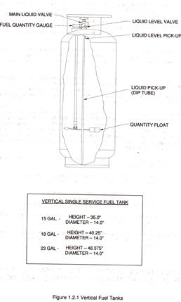
Most of my experience over the forty years of flying balloons has been in balloons with vapor pilot lights, as the balloon involved in the accident was described to have. In these balloons, the pilot light uses vapor delivered through a low-pressure hose from the top of the propane tank. The vapor evaporates from the liquid propane in the tank thus reducing the temperature of the propane due to evaporation. Liquid propane to the burners is delivered from the bottom of the tank through a metal tube inside the tank through a valve at the top of the tank and through a high-pressure hose to the burners. My flying experience since October, 2008, has been with pilot lights that run directly off the liquid delivered to the burners which is converted to vapor at the burner through a vapor converter and regulator; only one high-pressure hose is connected to the tank. This configuration should have a reduced impact on the liquid propane temperature in the tank since pilot-light vapor is not due to evaporation in the tank; temperature reduction of the liquid would only occur due to evaporation of the liquid in the tank to replace the fuel delivered to the burner and pilot. As the following development will suggest, the pilot light configuration could impact the properties of the propane and the performance of the balloon, especially at low propane levels. The main components of the fuel-burner system are shown at the end of this article. The propane tank is made out of 304 and 321 stainless steel.
Hypothesis
As propane is used to heat the balloon, evaporation takes place in the propane tank to replace the quantity of the liquid used, which causes the temperature and pressure of the liquid propane to decrease. As the liquid propane decreases during the operation of the balloon the amount of heat to evaporate the liquid is pulled from a smaller volume of liquid causing a more significant impact on the temperature of the liquid and on the pressure in the tank. Vapor pilot lights would tend to further lower the temperature and pressure of the propane during the balloon flight.
Calculations of
Pressure-Temperature Characteristics of Propane Fuel During the Flight of a Hot
Air Balloon Assuming Adiabatic Conditions for the Propane
The following theoretical development is based on simple heat transfer calculations. (That is all I know how to do.) The concept is that if a gallon of liquid propane is removed from the tank to power the balloon, a gallon of vapor must be evaporated to fill the space vacated by the liquid requiring heat to be removed from the liquid. The pressure of the propane is determined by the temperature of the liquid and the vapor pressure characteristics of propane. The amount of heat removed from the liquid is dependent on the heat of vaporization and the mass of the propane evaporated. Note that the calculations only relate to evaporation inside the tank; evaporation at the burner is supplied by heat from the burner itself at the heat exchanger and does not impact the temperature of the liquid in the tank. In my initial set of calculations of the pressure-temperature characteristics of the propane in the tank, I assume no additional heat is added to the liquid from other sources. I use the conditions of the balloon that I fly, that is, 15 gallon, stainless steel, propane tanks, which are the same tank sizes in the balloon involved in the accident. The tanks have insulated jackets. As mentioned earlier, the pilot lights in my balloon run off of liquid delivered to the burner through pilot converters. I don’t have data on vapor consumption by vapor pilot lights to consider in my calculations at this point.
For the following calculations, the propane tank has a liquid volume (VL) – initial value of 15 gal. – and vapor volume (VV) – initial value of 2.5 gal. As stated above, I assume an adiabatic process, no heat transfer from the outside to the propane. I will calculate the tank pressure as the liquid is reduced in multiple steps of ΔVL. As the liquid is reduced by ΔVL, the ΔVL is filled with vapor by evaporating the liquid; ΔVL = ΔVV.
The energy ΔH required to evaporate the necessary liquid to replace the vapor is described by:
(1) ΔH
= ΔVV x ρV x HV
Where ρV is density of the vapor
HV is heat of vaporization
ΔVV
is the volume of vapor necessary
to fill the volume of liquid removed.
The reduction in temperature of the propane ΔTP due to the evaporation is given by:
(2) ΔTP = ΔH / [(VL - ΔVL) x CPL x ρL + (VV + ΔVV) x CPV x ρV]
Where CPL is the specific heat at constant pressure for the liquid
ρL is the density of liquid
CPV is the specific heat at constant pressure for the vapor
ρV is the density of vapor
I cycled through iterations of the calculations with ΔVL equal to one gallon per cycle, calculating after each cycle the new temperature of the propane and corresponding pressure in the tank[1]. The tank pressure can be determined from Pressure-Temperature data for propane obtained from NIST tables on the internet at: http://webbook.nist.gov/cgi/fluid.cgi?ID=C74986&Action=Page
The Heat of Vaporization was obtained from “Handbook of Physics and Chemistry” published by the Chemical Rubber Publishing Co. (See Figs. 2 and 3).
These
data were fitted with second order polynomial regression trendlines in a
Microsoft Excel spreadsheet for use in
the calculations; all of the equations fit the data with R2 values
of at least 0.9997. The parameters of interest:
(3) ρV = 0.0054 T2 + 0.0.2726 T + 10.446; (T in ◦C;
ρV in
kg/m3)
(4) HV = -0.0018 T2 – 0.271 T +89.623; (HV in cal/g)
(5) ρL = -0.0051 T2 – 1.3215 T + 528.56; (ρL in kg/m3)
(6) CPL = 2e-5 T2 + 0.0016 T + 0.5988; (CPL in cal/g-◦C for liquid)
(7) PV = 0.031 T2 + 1.9888 T + 69.151; (PV is absolute vapor pressure in psia)
(8) CPV = 3e-5 T2 + 0.0019 T + 0.4168; (CPV in cal/g-◦C for vapor)
(9) Teq = -0.0009 PV2 + 0.5418 PV – 32.61; (Teq is equilibrium temperature-◦C)
For the following calculations, the volume units are gallons.

Figure 1. Heat of Vaporization for Propane

Figure 2 Pressure-Temperature Characteristics of Propane
Following the reduction of the liquid propane by ΔVL, the heat loss in the liquid propane necessary to evaporate ΔVV (equal to ΔVL) gallons of vapor can be calculated by substituting the above equations in:
(10) ΔHL = 3.79 x ΔVV x ρV x HV; (ΔH in calories)
The decrease in temperature in (VL - ΔVL) gallons of liquid becomes:
(11) ΔTP = ΔHL / [3.79 x {(VL - ΔVL) x CPL x ρL + (VV + ΔVV) x CPV x ρV}]; (ΔTP in ◦C)
The new temperature of the propane is then given by
(12) TP2 = TP1 - ΔTP
The resulting equilibrium vapor pressure can then be calculated by:
(13) PV2 = 0.031 (TP1 - ΔTP)2 + 1.9888 (TP1 - ΔTP) + 69.151
where TP1 is the initial temperature of the propane.
The gauge pressure, PG, is calculated by subtracting the absolute ambient atmospheric pressure of 12.5 psi from the absolute pressure PV; 12.5 psi is the atmospheric pressure at Albuquerque’s altitude above sea level.
The reduction in the volume of liquid due to the evaporation, ΔVLE, of ΔVV gallons of vapor is given by
(14) ΔVLE = ΔVV x ρV/ρL
Following thermal equilibrium, which I will assume occurs rapidly with respect to the time that the liquid is removed, the calculation cycle can be repeated using the starting conditions determined by the previous calculations, with a volume of liquid, VL2, equal to the previous volume reduced by (ΔVL + ΔVLE), a new temperature equal to the previous temperature reduced by ΔTP, and a new pressure of PV2.
Adiabatic Results –
Propane Only
These calculations were made using the above equations with the initial volume of propane of 15 gallons, and ΔVL steps of one gallon. Initial gauge pressure was assumed to be 100 psig equivalent to 112.5 psia, corresponding to an equilibrium temperature of 62.5 ◦F. The calculations were carried through 14 cycles, and the results are presented in Fig. 3 and Fig. 4. Thermal equilibrium was assumed to take place over the time required to removed the propane due to the short bursts of propane withdrawal and time in between bursts.

Figure 3. Calculated propane pressure vs. %
propane remaining in the tank.
Propane only included in calculations.
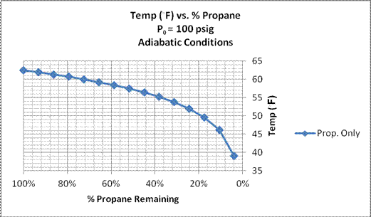
Figure 4. Calculated propane temperature vs. %
propane remaining in the tank.
Propane only included in calculations.
Another
result of the calculations was that 0.42 gal. of propane was evaporated in the
process of replenishing the tank with vapor as the liquid propane was used,
leaving the tank with 0.58 gal. remaining after 14 cycles of the calculations.
While
these results demonstrate the effect initially proposed in that the temperature
and pressure of the propane decrease during operation of the balloon due to
evaporation of the propane necessary to replace the volume of liquid removed
during operation, the effect would be less if heat from the stainless steel
tank was considered. So the next set of calculations were made to include the
temperature of the tank.
Calculations of
Pressure-Temperature Characteristics of Propane Fuel During the Flight of a Hot
Air Balloon Assuming Adiabatic Conditions for the Propane and the Stainless Steel
Tank
In the following calculations I will assume the stainless steel tank and the propane remain in thermal equilibrium under adiabatic conditions. The heat lost due to evaporation in eq. (1) is now dispersed in the propane and the stainless steel tank, and eq. (2) become
(15) ΔTP = ΔH / [(VL - ΔVL) x CPL x ρL + (VV + ΔVV) x CPV x ρV + Mss x Css]
Where Mss is the mass of stainless steel
Css is the specific heat of stainless steel
In this example I used heat capacity for 304 and 321 stainless of 54.2 cal/lb-◦C with a mass of 40 lbs. Eq. (11) for the change in temperature of the propane becomes
(16) ΔTP = ΔHL / [3.79 x {(VL - ΔVL) x CPL x ρL + (VV + ΔVV) x CPV x ρV} + 54.2 x 40]
A new set of calculations were then performed using Eq. (10), Eq. (12) through Eq. (14), and Eq. (16) to calculate the temperature, pressure and volume of the propane including the thermal effects of the stainless steel tank. Typical values for ΔH were about 5000 cal. for each gallon of evaporated vapor, and ΔTL ranged from about 0.5 to 7 ◦F. The results are shown in the following figures.
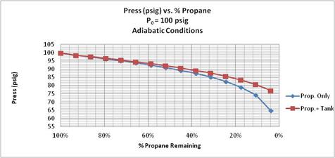
Figure 5. Propane Pressure vs. % Propane Remaining for two adiabatic calculations: with propane only, and with propane and 40 lb. stainless steel tank. Initial propane pressure = 100 psig.
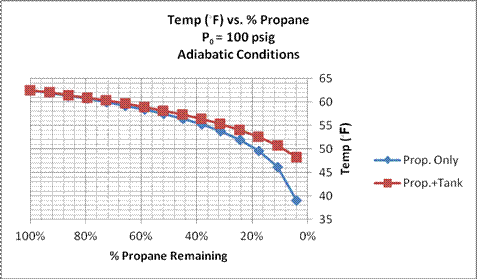
Figure 6. Propane Temperature vs. % Propane Remaining for two adiabatic calculations: with propane only, and with propane and 40 lb. tank. Initial propane pressure = 100 psig

Figure 7. Change in temperature of the propane per gallon removed, ΔTP (◦F), vs. % Propane Remaining for two adiabatic calculations: with propane only, and with propane and 40 lb. tank. Initial propane pressure = 100 psig.
Another set of calculations was performed with an initial propane pressure of 90 psig, a starting pressure within the safe operating conditions for the balloon. Those results are presented in the next two figures.
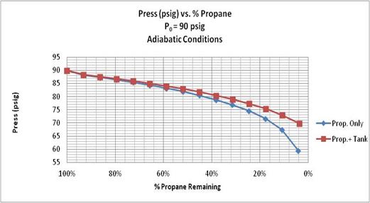
Figure 8. Propane Pressure vs. % Propane Remaining for two adiabatic calculations: with propane only, and with propane and 40 lb. tank. Initial propane pressure = 90 psig.
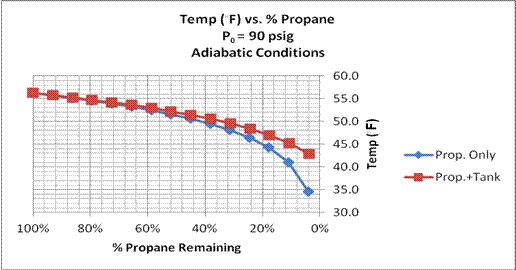
Figure 9. Propane Temperature vs. % Propane Remaining for two adiabatic calculations: with propane only, and with propane and 40 lb. tank. Initial propane pressure = 90 psig.
Comparison of Calculations
with Experiment (April 12, 2014)
To
compare these calculations with real balloon operations, I monitored a flight
on my balloon, an Aerostar S55A with vapor-converter pilot lights, on April 12,
2014. The tanks were not heated overnight because the ambient temperature had
been in the low 80’s the day before, and the propane pressure remained
satisfactory for the early morning flight. The flight began about 0730 with an
ambient temperature of about 47 ◦F. The propane pressure after
inflation was 100 psig in both propane tanks, 15 gal., steel tanks with thermal
insulation jackets. Propane pressure and percent propane in both tanks were
monitored and recorded at several points during the flight. The flight was
terminated at about 0840 after several take-offs and landings, one more like a
“crash and drag”. One tank showed 47% propane remaining with a pressure still
at 100 psig, and the other tank was at 35% with pressure of 93 psig. After tipping
over the basket and detaching the envelop from the gondola, the basket was set
back in the upright position, and the burner using the tank with the lower
pressure was operated in several bursts over next 20 minutes until the propane
level reached about 7.5% with pressure of 80 psig. At 0900 the ambient
temperature had increased to 54 ◦F. These data are summarized
in the following table.
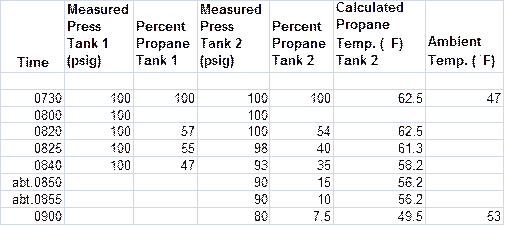
Figure 10. Recorded data for balloon flight on 4/12/2014. Note the level of propane in the tank does not register until it is less than 60%.
The data for Tank 2 are plotted in the next two figures along with the calculated results for 100 psig propane pressure in a 40-lb. steel tank. The calculated propane temperature is the equilibrium temperature based on the tank pressure as shown in Eq.(9). Note the pressure in Tank 1 did not vary over the first 70 minutes of flight, indicating that external air temperature was not a factor in the tank pressure. I failed to record the Tank 1 pressure at the end of the experiment at 0900.
Figure 11. Propane pressure vs. percent propane remaining. Experimental data during balloon flight on April 12, 2014, and calculated adiabatic results for propane in 40 lb. steel tank . The solid curves are regression trend lines calculated in a Microsoft Excel spreadsheet.
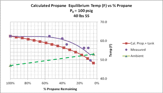
Figure 12. Calculated equilibrium temperature of the propane [Eq. (9)] for experimental flight tests and theoretical results. Also shown is the ambient temperature at beginning and end of the balloon flight.
Comparison of Calculations
with Experiment (May 12, 2014)
Following the experimental balloon flight on April 12, I decided to do a more controlled experiment that was not restricted by the vagaries of a balloon flight. This entailed monitoring the propane properties during operation of the burner-propane system with the balloon gondola in a stationary position. We had flown the balloon the day before on May 11, so the propane tanks needed to be refilled. After refilling the tanks at about 3:00 pm on May 12, I began a series of operating one of the burners for Tank 1 for about five seconds every 15 to 20 seconds and monitoring the pressure at the burner. The other tank, Tank 2, and burner were not operated except for checking the pressure periodically to determine if other factors were influencing the data taken on the first burner, such as pressure changes due to non-adiabatic effects.
The data from these tests are shown in the next figure.
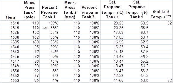
Figure 13. Experimental data taken on May 12, 2014.
From these data, we see that the pressure on Tank 2 remained constant indicating no impact on the propane pressure due to external thermal effects; i.e., adiabatic conditions prevailed over the time of the experiment. During operation the pressure on Tank 1 decreased from 110 psig to 85 psig as the percent propane remaining in the tank decreased from 100 percent to four percent. The calculated equilibrium propane temperature decreased from 68 ◦F to 53 ◦F. Ambient temperature remained constant at 62 ◦F.
These data are plotted in the next two figures along with the theoretical calculations for an initial propane pressure of 110 psig.
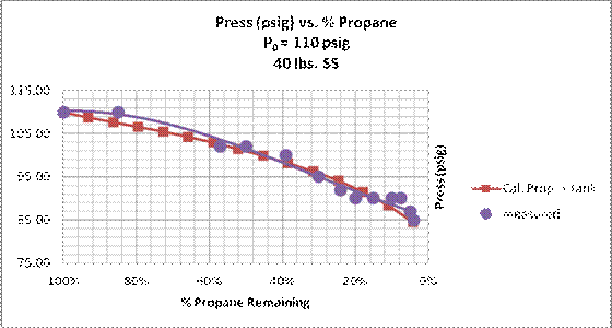
Figure 14. Propane pressure vs. percent propane remaining. Experimental data and calculated adiabatic results for propane in 40 lb. steel tank . The solid curves are regression trend lines calculated in a Microsoft Excel spreadsheet. Stationary test conditions on May 12, 2014.
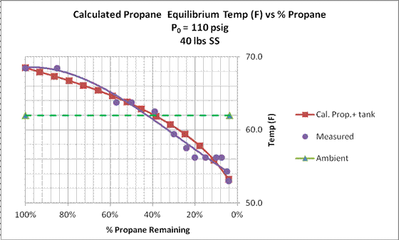
Figure 15. Calculated equilibrium temperature of the propane [Eq. (9)] for experimental and theoretical results. Also shown is the ambient temperature at the beginning and end of the test sequence.
These test results agree very nicely with the calculations indicating that thermal equilibrium was maintained as the burner was operated. So what is the difference between these test results and the earlier results for the balloon flight where thermal equilibrium was not achieved until the very end of the test? In the first test the propane tanks were loaded into the truck on a warm afternoon and left overnight exposed to the outside temperature which decreased from the low 80’s to 47 ◦F. This exposure created thermal gradients in the liquid propane with warm propane at the top of the tank and cooler propane at the bottom. So during flight the colder propane at the bottom of the tank was used first leaving the warmer propane at the top which determined the vapor pressure. The propane did not reach equilibrium until the end of the test when all of the heat necessary to replenish the vapor in the tank had been extracted from the liquid. In the case of the test on May 12 , the propane had not had time to set up thermal gradients after refilling the tanks only a few minutes prior starting the tests. In this case, thermal equilibrium was maintained throughout the test.
Estimate of the
Impact of Thermal Diffusion in the Liquid Propane on Balloon Performance
The difference between the experimental results and the calculations for the April 12 test is probably due to the assumption of thermal equilibrium for the liquid propane during operation. The difference narrowed as the propane level was reduced, probably because the smaller volume of propane was more closely approaching thermal equilibrium.
One explanation of the lack of equilibrium over the time scale of the balloon flight could be due to the differences in thermal diffusivity values for liquid and vapor propane, and stainless steel, about 7.5 x 10⁻⁴ cm2/s for liquid, 6.4 x 10⁻³ cm2/s for vapor, and 0.042 cm2/s for stainless. These values would indicate that the liquid would lag the other two constituents in reaching equilibrium. This can be seen in the following graphical displays of solutions to the one-dimensional diffusion equation for the different materials given by
(17) E(x,t) = Φ/(4πDt)1/2 exp(-x2/4Dt)
where E(x,t) is energy density in the material (cal/cm3)
x is distance into material from the surface at x=0 (cm)
t is time (sec)
Φ is energy flux deposited in the material at x=0 (cal/cm2)
D is thermal diffusivity (cm2/sec)
Results for two calculations at t= 1 sec. and t=5 sec. are shown in the next two figures for the three materials, liquid propane, propane vapor and stainless steel. With about 5000 calories withdrawn with the evaporation of one gallon of vapor, the energy flux at the surface of the liquid would be about negative 5 cal./cm2 with a tank diameter of 14 inches.
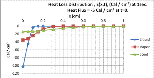
Fig. 13.
Heat loss distribution in liquid propane, propane vapor and stainless steel at
t=1 sec after removal of 5 cal/cm2 at x=0 and t=0.
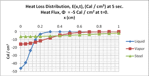
Fig. 14.
Heat distribution in liquid propane, propane vapor and stainless steel at t=5
sec after removal of 5 cal/cm2 at x=0 and t=0.
From these figures, we see in Fig. 13, in one second, the heat loss is distributed in the liquid propane to about 0.1 cm., for propane vapor about 0.2 cm, and for stainless about 0.5 cm. In Fig. 14, at five seconds, the depths respectively are about 0.2 cm, 0.5 cm and one cm. The walls to the stainless steel tank are 0.19 centimeter thick, so the heat to the wall would be conducted along the walls of the tank in a two-dimensional manner through the wall and along the vertical axis. Given the dimensions of the tank, thermal gradients would persist for much longer periods than those depicted here. The slowest to reach equilibrium would be the liquid propane. The time necessary for the propane to reach a heat loss distribution of 10% of the surface value, t0.1, at depth d cm. can be determined using Eq. (17)
(18) E(d,t0.1)/ E(0,t0.1) = 0.1 = exp(-d2/4Dt0.1) and solving for t0.1 giving
(19) t0.1 = 144.7 d2 for the liquid propane.
Or solving Eq.(19) for d gives
(20) d = (t0.1
/ 144.7)1/2
Applying this equation to the conditions in Fig. 14, gives d = 0.19 cm., compared to the visual estimate of about 0.2 cm.
During a 100 min. balloon flight, the heat loss in the liquid propane due to diffusion would extend only about 6.4 cm. from the liquid surface. Assuming the original height of the 15 gallons of propane in the tank to be about 30 in. or 75 cm, a gallon of propane would occupy a height of 5 cm. in the tank. So the heat removed from the propane during the flight would be concentrated in the last gallon or two left in the tank, assuming all the liquid removed came from the bottom of the tank and the heat loss due to evaporation was propagated in the liquid by diffusion. The temperature of the steel tank would be more reflective of the bulk of the liquid propane and remain higher than the surface temperature of the liquid during the early portion of the flight. The pressure in the tank would be determined by the average temperature of the propane and remain higher than would be expected based on the temperature of the liquid surface. These unbalanced temperatures are reflective of the lack of thermal equilibrium in the overall system. They would converge only near the end of the flight at low propane levels. Of course, any mixing of the liquid propane or convection currents would also reduce the thermal gradients in the propane.
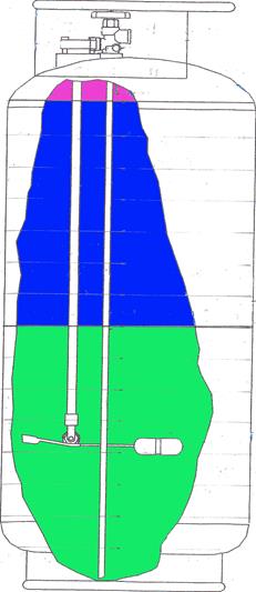
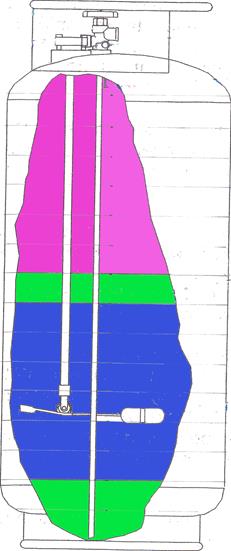
However, using this approximation is instructive in helping to understand the original test results when thermal gradients were present in the liquid prior to flight. Schematic depictions of the propane with thermal gradients in the tank are shown in Figs. 15 through 17. Figure 15 depicts the tank conditions prior to the flight; vapor is shown at the top of the tank, warm propane is shown below the vapor in the upper portion of the tank, and cool propane is depicted at the bottom. (The picture is graphic only; there would not be a sharp delineation of warm from cool propane as shown, but a gradual change over the depth of the tank). Figure 16 depicts the propane distribution when the tank is about half full. A cool layer of propane is shown at the top of the liquid due to evaporation of the vapor to fill the top half of the tank. The cool propane has been removed from the bottom and the warm propane has moved down. The pressure in the tank would reflect the warmer temperature of the propane and remain higher than it would have been without thermal gradients in the propane. Figure 17 depicts the propane near the end of the flight, where even most of the warm propane has been removed, and the cool layer at the top of the liquid is deeper than earlier in the flight. In this situation the pressure would reflect the cooler conditions of the propane and could be significantly lower than earlier in the flight. This is shown in the measurements of April 12 where the pressure remained higher than is predicted under equilibrium conditions, and dropped faster during the last part of the tests compared with the earlier time in the flight and what would have been the case with thermal equilibrium.